Some Synfig Basics
posted on Feb 7, 2018 by Meg James
Synfig Studio appears to be a good program used to make vector animations, kind of like Flash. Synfig was used to create the short film Lūdō, by L James. However, I don’t yet have much experience in Synfig. Thinking ahead to making short films, I thought it would be worth a try.
Where to begin
After putting together storyboards for a short film idea, I figured the logical place to begin would be by making a model sheet for a character – in this case, Darius from Bottle World: Explore. A model sheet would make it easier to animate the character later, and also provide practice for drawing in Synfig. So how do you draw in Synfig? One of the most important tools is this:
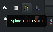
The spline tool.
The spline tool is Synfig’s basic bezier curve tool. I’m assuming you already know how to use a pen tool or bezier curve tool. If you don’t, take some time and practice drawing and making shapes with this tool. The basic drawing process using the spline tool is straightforward. It works much like the pen tools in other software. However, Synfig’s spline tool has some specific quirks. I had a little trouble with it, which strongly influenced how I ended up drawing this model sheet. There are many options for creating a spline:
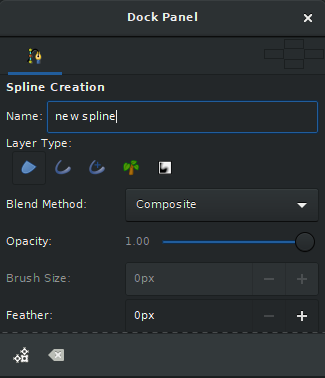
Spline tool dock panel.
In the spline tool’s dock panel, before you create your spline, you can choose the layer type you want to make. For Darius’s model sheet, I ended up only choosing the first of these layer types, which is a “region” layer. However, there are multiple other options and you can choose any or all of them. When choosing only the “region” type, this is how it looked when I drew shapes.
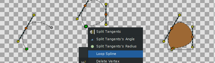
Looping a spline.
I had originally wanted to include an “outline,” in addition to the “region.” However, when looping splines that have outline layers, the outlines automatically close.
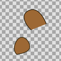
Looped spline (bottom) with unlooped spline (top).
With how parts can overlap in character models, and myself not realizing I didn’t have to loop all my splines, I opted for a lineless style to avoid weird extra outlines where they weren’t needed. However, for the record, you can avoid looping a spline by just selecting a different tool after making your last vertex. The Transform tool is as good a choice as any.
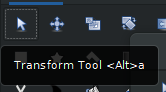
Transform tool.
I didn’t figure this out until part of the way through drawing the model sheet, hence why I went without outlines altogether.
After you draw several splines, you might want to know how to color them. There are a couple ways to do this.
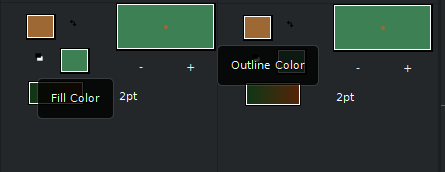
Fill color and outline color.
One way to edit the color can be done before drawing your next spline. You can see the fill color and outline color in the Synfig interface. Clicking on either of these will open a menu where you can select a new color.
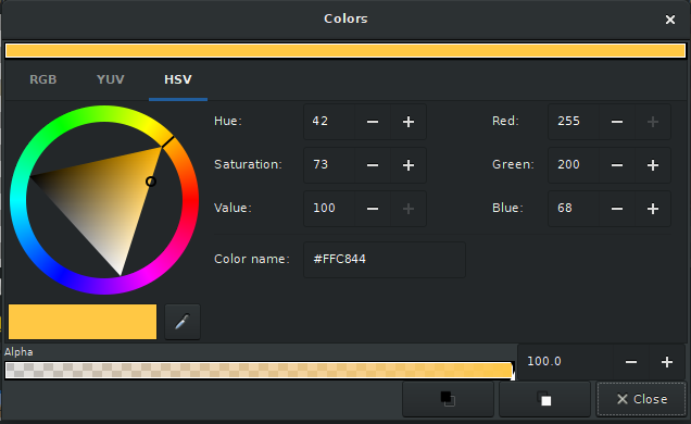
Color selection.
Any splines you draw after changing the color will be in the color you chose for the fill or outline. If you’ve already drawn a bunch of splines and need to change the colors of those, that can be done as well. Select the spline layer you want to edit, then look down in the “parameters” section.
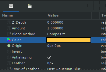
Editing color from the Parameters section.
Down in the parameters, you will be able to click on the color block to open up the same color-choosing menu as before. Doing this will only change the color of whatever layer you have selected. This won’t change your current fill or outline color.
Once you can make and recolor splines in Synfig, you are almost all-powerful! But how do you put these splines together in a way that makes sense?
Building a character
With animation in mind, an important factor in this kind of model sheet is considering how easy it will be to move the character. Synfig lends itself great to moving parts, since each spline is its own layer. Also, vector shapes are easy to move, rotate, and mangle without quality loss. Before jumping in and drawing, stop and think about how the character will be moving. You think you can draw the entire leg as one shape? What if you want to bend it at the knee, huh??
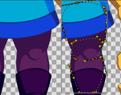
Selection of the leg’s base color, showing that it is two shapes.
Basic coloring and a simple drawing style make it easy to disguise multiple pieces as a single solid shape, as with this leg, used for example. There is a distinct shape for the thigh and another for the calf. The lighting on the calf is also a separate layer, as is the lighting for the knee. As mentioned, a simple character design works great for this. If you’re working on one of your first projects, simple is pretty good to start with.
As you can imagine, having so many moving parts is going to result in a lot of layers. Although this is handy if you need to edit or move individual parts, it could get hard to keep track of.
Organizing layers in Synfig
So once you figure out how to draw shapes to your liking, and determine how to break down your character design into multiple parts to make animating later less of a nightmare, you may start looking at your layers and realizing there are going to be tons of them. Luckily, it’s pretty easy to move, group, and rename layers in Synfig.
To name a spline before you create it, the dock panel for the spline tool has a section for the layer’s name.
Spline tool dock panel, with the spline name set to “new spline.”
However, if you’re anything like me, you’re probably not choosing new names for each spline as you go along. Rather, you may be renaming several layers at a time as you realize that everything on your model sheet is called “new spline” or something. Fear not, renaming an existing layer is easy to do.
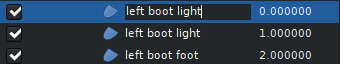
Double click on the layer name to rename it.
To rename any layer, all you need to do is double-click on the layer’s name. When you’re done typing the new name, either hitting your “enter” key or clicking anywhere outside the layer name should finish the renaming process.
As you draw a character model, you may also run into the issue of drawing things in the wrong order. That is, you may have splines in front of other splines that should appear behind others, instead. Luckily, reordering layers is also straightforward.
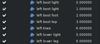
Synfig assigns “Z Depth” numbers to layers.
The spline layers that are higher up on the layer list will appear in front of other splines. In the layer section, there will also be a column labeled “Z Depth,” which indicates the relative positions of your layers in terms of how far back or forward they are. A spline layer Z Depth of “0” is on the top, for example, and this spline will appear over any other splines.
If you have a spline that needs to be moved either in front of or behind another, you can either click and drag the layer to a lower or higher position in the list, or you can use the “Raise Layer” and “Lower Layer” buttons at the bottom of the layer section.
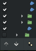
Raise/lower layer buttons.
A final tip for organization is to use groups. Groups are easy to make. There is a green folder icon at the bottom of the layer section. Clicking on this will create a “group” layer. You can also click on this folder icon while you have one or more layers selected. This will place the selected layers into a group together.
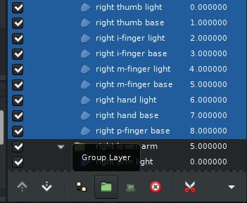
Selecting layers to group.
Groups are handy for keeping things organized. You can even put groups within other groups, which can be incredibly helpful.
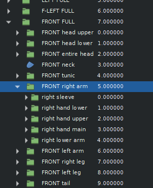
Groups within groups within groups!
Once you know how to reorder, rename, and group layers, it shouldn’t be much trouble to keep your splines organized.
What comes next?
For me, starting to draw a model sheet in Synfig was only the first step. I learned a lot as I went along. The process took way longer than expected since I kept realizing how much detail I needed in the model sheet.
This is already coming out to a pretty long post, so my next post will be about determining what you need from a model sheet.
You must be a member to post comments.